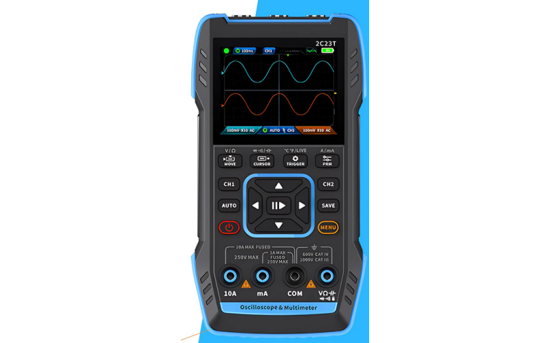
How to Check CAN Network Using an Oscilloscope | Step-by-Step Guide

1. Prepare and Calibrate High-Precision Equipment
Tools Required:
- Digital Oscilloscope: Use a high-bandwidth (100+ MHz) oscilloscope with at least 1 GS/s sampling rate to accurately capture the fast transitions on CAN networks.
- Differential Probes: Essential for high-accuracy readings on CAN_H and CAN_L without ground interference. Select probes rated for the expected voltage range and bandwidth of your network.
- Termination Checkers: Check for 120-ohm termination resistors at both ends of the CAN bus.
- CAN Protocol Decoder Module (Optional): Many advanced oscilloscopes offer built-in protocol decoding for real-time CAN message display, which can assist in troubleshooting.
Calibration:
- Probe Calibration: Calibrate probes with the oscilloscope’s built-in calibration routine. Proper calibration is vital for high-accuracy measurements.
- Compensation Adjustment: Verify probe compensation by connecting to a known square wave. Properly compensated probes ensure accurate signal readings.
2. Configure Oscilloscope for Advanced Signal Capture
- Connection: Attach the differential probe across CAN_H and CAN_L. Avoid grounding probes on CAN lines directly; use the differential setup to prevent ground loops.
- Time Base & Sample Rate: Set the time base to 5–10 µs/div for an initial view, adjusting based on message speed and frame detail. Set a high sample rate (at least 10x the highest expected signal frequency) for clear transitions.
- Voltage Scaling: Start with 2V/div or 5V/div. Proper scaling enables observation of fine signal details and voltage fluctuations.
- Triggering Setup:
- Edge Trigger: Configure to capture rising or falling edges at 2.5V (the typical midpoint for CAN).
- Pulse Width Trigger: For capturing data pulses outside standard durations, set the pulse width trigger to detect any unusually long or short pulses.
- Glitch Trigger: This helps capture transient errors or reflections, especially useful for identifying intermittent issues.
3. Decode the CAN Signal (Optional, but Recommended)
Many oscilloscopes support CAN protocol decoding. Use this feature for direct visualization of CAN message frames and IDs.
- Configure Data Rate: Match the baud rate of your CAN network (e.g., 500 kbps or 1 Mbps).
- Set Threshold: Align the threshold to 2.5V to capture both high (dominant) and low (recessive) states accurately.
- Enable Filtering: Filter by message ID or data type for detailed analysis, helpful in networks with high traffic.
4. Analyze Signal Quality and Integrity
- Differential Signal Verification: Ensure the differential voltage between CAN_H and CAN_L is approximately 2V during dominant states (CAN_H at ~3.5V, CAN_L at ~1.5V). Incorrect differentials suggest potential issues with wiring or termination.
- Frame Pattern Consistency: CAN frames have specific start-of-frame, identifier, data, CRC, and end-of-frame sections. Confirm a consistent pattern across frames.
- Rise/Fall Time: Examine the rise and fall times. Excessive slopes may indicate capacitance issues or overloaded networks.
5. Troubleshoot Common CAN Issues
- Reflections and Echoes: Reflections typically indicate termination issues or impedance mismatches. Reflections appear as echo signals following the main pulse. Check both ends for 120-ohm termination resistors.
- Noise and Grounding Issues: Transient noise or interference spikes on the waveform suggest poor grounding or electromagnetic interference (EMI). Use a probe ground loop suppressor if available.
- Bit-Stuffing Errors: CAN networks use bit-stuffing to ensure frame synchronization. Unexpected extra bits within frames may indicate a synchronization issue or physical layer fault.
6. Diagnose and Interpret Error Frames
CAN networks automatically generate error frames when communication issues arise. Look for:
- Error Frames: Bursts of six or more dominant bits indicate an error frame, often due to a physical layer issue or overloaded network.
- Bit Errors: Frequent bit errors in specific segments suggest localized network faults, such as damaged connectors or cables.
- Bus Arbitration Issues: Collisions may occur if multiple nodes attempt transmission simultaneously, resulting in error frames. Observe and record the frequency and context of collisions.
7. Evaluate Network Load and Latency
- Network Load Measurement: High bus loads (close to 100%) can lead to delays and increase the chance of collisions. Measure network load by observing message intervals and frequency.
- Latency Calculation: For real-time applications, monitor the time delay from one node to another. Latency issues may require network reconfiguration to prioritize essential messages.
8. Document, Compare, and Analyze Data
- Capture and Save Waveforms: Store waveforms for post-analysis or future reference, which helps in pattern recognition and progressive diagnosis.
- Compare Against Reference Waveforms: Refer to standard CAN frames to identify irregularities in captured data.
- Create a Report: Document key findings, including waveforms, observed errors, and identified issues. This report can help with repair decisions, future diagnostics, and maintenance records.
By following these advanced techniques, you can gain a comprehensive understanding of your CAN network’s health, identify complex issues, and ensure reliable communication between devices.
Posted by
System Administrator
Cars
views (409)


